
A Practical Guide to the Craniofacial Reference Used to Standardize Head Position
The Frankfort plane, more fully called the Frankfort horizontal plane, is an imaginary reference used to orient the head consistently. Dental professionals,…
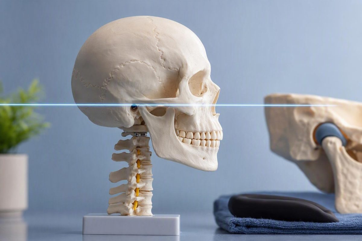
The Frankfort plane, more fully called the Frankfort horizontal plane, is an imaginary reference used to orient the head consistently. Dental professionals, orthodontists, surgeons, photographers, anthropometrists, and researchers use it to reduce variation caused by head tilt and make images or measurements easier to compare.
Its defining skeletal landmarks are orbitale, at the lower margin of the eye socket, and porion, at the upper margin of the external ear canal. On a side-view image, the reference appears as a line joining those points. In three dimensions, however, a plane requires a more explicit construction using landmarks from both sides of the skull.
That distinction is fundamental. The Frankfort plane is useful, but it is not automatically identical to true horizontal, a person’s natural head position, or the dental occlusal plane.
What Is the Frankfort Plane?
The Frankfort horizontal plane, often abbreviated FH or FHP, is an imaginary craniofacial reference based on two named skeletal landmarks:
- Orbitale: the lowest point on the inferior margin of the orbit, or eye socket.
- Porion: a point at the upper margin of the external auditory meatus, the bony ear-canal opening.
In a profile view, FH is commonly drawn as a straight line from porion to orbitale. This porion-to-orbitale construction is one of the references used to assess dental, skeletal, and soft-tissue relationships on a lateral cephalogram.
Calling it a “plane” while drawing a “line” is not a contradiction. A lateral radiograph or profile photograph presents a two-dimensional view of a three-dimensional head.
The central purpose of FH is standardization. Orienting the head to a defined reference reduces that source of variation.
Depending on the setting, the Frankfort plane can help professionals:
- Position the head for certain radiographs.
- Trace and compare cephalometric relationships.
- Standardize facial photographs.
- Repeat cranial or facial measurements.
- Monitor growth or treatment-related changes.
- Transfer an anatomical orientation to selected dental instruments or models.
It does not identify disease by itself. It functions more like the baseline on a graph: it establishes the orientation from which other structures are described and measured.
Orbitale, Porion, and the Landmark Terms That Cause Confusion
Understanding the Frankfort plane requires more than locating “the eye” and “the ear.” Its formal points are specific anatomical landmarks, and several nearby terms are sometimes used loosely.
Orbitale
Orbitale is a skeletal point on the lowest part of the inferior orbital margin. In everyday language, it is the lowest point along the bony lower rim of the eye socket.
It is not simply the skin below the eye, the lower eyelid, or the center of the cheek. Those visible features may help an operator estimate the underlying location, but they are not themselves the formal bony landmark.
On a radiograph or three-dimensional scan, orbitale is identified from bone. In a photograph or direct external measurement, the operator may need to estimate or palpate the corresponding location. That difference in method can affect the resulting reference.
Porion
Porion is the skeletal landmark associated with the uppermost margin of the external auditory meatus. It is not merely any visible point around the ear opening.
Its identification may depend on the imaging method, equipment, and landmark convention. Nearby structures can overlap on a radiograph, while the bony upper canal margin is generally not directly visible on a living person.
Tragion and the supratragal notch
Tragion is an external soft-tissue landmark near the upper border of the tragus—the small cartilaginous projection in front of the ear canal. Some protocols place it in the notch immediately above the tragus, often called the supratragal notch.
These external landmarks are convenient in photography, anthropometry, and bedside positioning because skeletal porion cannot usually be seen through the skin. For example, an otolaryngology glossary describes a photographic Frankfort reference using the inferior orbital rim and the supratragal notch or tragion for standardized preoperative photography.
Convenience does not make these terms interchangeable:
- Porion is a skeletal landmark at the upper auditory-meatus margin.
- Tragion is an external soft-tissue landmark in the tragal region.
- Supratragal notch describes an externally accessible notch above the tragus.
- Ear opening names a broad visible region rather than a precise craniometric point.
A protocol may use tragion as a practical substitute for porion, but a technical report should say so. It should not claim to have used skeletal porion if the actual point was an external soft-tissue approximation.
This distinction is especially important when comparing photographs with radiographs or cone-beam computed tomography scans. Two analyses may both be labeled “Frankfort horizontal” while using different physical points.
Terminology also varies by task. A photographic protocol may reasonably specify an externally visible ear landmark. A cephalometric study may use radiographic porion. An anthropometric protocol may adopt another operational definition. The safest practice is to document:
- Whether the landmarks were skeletal or soft-tissue points.
- Which side or sides were used.
- How each landmark was identified.
- Whether the reference came from a photograph, radiograph, scan, or direct measurement.
Why a Plane Becomes a Line in 2D—and How 3D Definitions Differ
A lateral cephalogram is a standardized side-view radiograph used to examine craniofacial relationships. It collapses a three-dimensional head into a two-dimensional projection, so structures from the left and right sides may overlap.
In that projection, the Frankfort plane is traced as a porion-to-orbitale line. The line provides a baseline against which points, distances, and angles can be assessed. Lateral cephalograms support orthodontic diagnosis and treatment planning, evaluation related to orthognathic surgery, and serial assessment of growth or tooth movement.
This two-dimensional construction is appropriate when the analysis is itself being conducted within a lateral projection. It does not, however, completely specify a unique three-dimensional plane.
Geometrically, a plane requires three non-collinear points or another expressly defined construction. Because the skull has left and right orbital and ear-canal landmarks, three-dimensional FH methods can use different combinations of the bilateral points or their midpoints. One historically reported construction uses left porion, right porion, and left orbitale. Other tested methods have used one porion with both orbitales, bilateral midpoint combinations, or a fitted plane based on all four landmarks in three-dimensional cephalometric analysis.
Changing the points can change the plane’s orientation. No single bilateral construction should therefore be assumed merely from the phrase “the Frankfort plane.”
A three-dimensional report should state:
- Which left and right landmarks were selected.
- Whether bilateral landmarks were averaged into midpoints.
- Whether the plane was defined from three points or fitted to four.
- How asymmetry or uncertain landmarks were handled.
- Whether the skull was reoriented before measurements were calculated.
The profile line and the anatomical plane are related, but they are not identical objects. The line is an appropriate two-dimensional representation; a three-dimensional model requires an explicit bilateral setup.
How the Frankfort Plane Is Used in Different Settings
The Frankfort plane performs the same broad job across several fields—establishing a repeatable orientation—but the landmarks and positioning instructions vary by procedure.
| Application | Landmark representation | Usual orientation | Purpose |
|---|---|---|---|
| Lateral cephalometry | Radiographic porion-to-orbitale line | Commonly oriented horizontally during acquisition or analysis | Standardize tracing and assess dental, skeletal, and soft-tissue relationships on lateral cephalograms |
| Panoramic dental imaging | Anatomical regions or an externally guided approximation | FH or the occlusal plane typically placed approximately parallel to the floor, depending on the machine | Support consistent head positioning; some units provide a horizontal alignment light |
| Facial or preoperative photography | Visible or palpated approximations near the inferior orbital and tragal regions | Often placed parallel to the horizon | Reduce apparent differences caused by head tilt |
| Anthropometry | Directly identified or approximated craniofacial landmarks | Aligned to the protocol’s defined horizontal reference | Make repeated head and facial measurements more comparable |
| Recumbent infant length | Externally located Frankfort reference as specified by the measurement protocol | Parallel to the fixed headpiece and perpendicular to the table | Maintain consistent head position during infant-length measurement |
| Prosthodontics | Anatomical or transferred reference related to porion and orbitale | Applied according to the face-bow or articulator method | Provide a craniofacial guide for cast orientation or occlusal-plane construction |
| Three-dimensional cephalometry | Expressly defined bilateral porion and orbitale combination | Reoriented within a stated coordinate system | Provide a reference for three-dimensional distances and angles |
Lateral cephalometry
In lateral cephalometry, FH provides a baseline for tracing craniofacial relationships. Clinicians may use the resulting analysis to assist orthodontic diagnosis and treatment planning, evaluate skeletal and dental relationships before orthognathic treatment, or compare serial images during growth or treatment.
Consistency matters as much as the nominal line. A difference between two tracings may reflect anatomy, growth, treatment, head orientation, landmark selection, or a combination of these factors. Repeating the same acquisition and tracing convention helps separate genuine change from methodological variation.
Panoramic dental imaging
A typical positioning protocol places the Frankfort or occlusal plane approximately parallel to the floor, although the exact instruction depends on the equipment.
This is a procedure-specific convention, not a universal instruction for every machine. Equipment designs differ, and manufacturers may specify a particular chin position, bite block, alignment light, or alternative reference. Clinical radiography should be performed by trained personnel following the relevant equipment and facility procedures rather than a generic online rule.
Standardized facial photography
Standardized photographic positioning makes before-and-after or repeated images more comparable by reducing variation caused by pitch.
The skeletal points are not directly visible in this setting. A photographer may instead use the lower orbital region and a tragal or supratragal landmark, creating a practical external approximation rather than a direct skeletal construction.
Good photographic standardization requires more than FH alignment. Repeating the complete protocol is more informative than matching one line while changing other conditions.
Anthropometry
Anthropometry involves systematic measurement of the human body. For cranial and facial measurements, a common orientation allows dimensions and angles to be collected from a consistent starting point.
The reference can improve comparisons across repeated sessions, observers, individuals, and measurement methods. It does not eliminate uncertainty: operators must still identify the landmarks consistently, and an external approximation may not reproduce the underlying skeletal plane exactly.
Recumbent infant-length measurement
Infant-length measurement illustrates why “horizontal” does not always mean “parallel to the floor.” The child is lying down, so the relevant relationship is to the measuring device.
In the cited protocol, the Frankfort reference is placed parallel to the fixed headpiece and perpendicular to the measuring table. The principle is the same as in upright positioning: orient the head consistently for the specific task.
Prosthodontics
In prosthodontics, FH may be used when transferring the orientation of the upper jaw to an articulator or when choosing a guide for occlusal-plane construction. The goal is to relate a dental cast or prosthesis to a reproducible craniofacial reference.
Its usefulness does not require exact parallelism between FH and the dental occlusal plane. A reference can remain clinically useful while having a variable angular relationship to the structure being constructed.
Does the Frankfort Plane Represent Natural Head Position?
Not necessarily.
Natural head position is generally described as the posture a person adopts while sitting or standing comfortably and looking at a distant point at eye level. It is intended to capture an individual’s visual orientation under defined conditions rather than force the head to match a cranial line.
Three concepts should be kept separate:
- Frankfort horizontal plane: an anatomical reference constructed from specified landmarks.
- True horizontal: a level line or plane defined relative to the environment and gravity.
- Natural head position: the posture adopted by an individual under a stated viewing condition.
Many clinical and photographic protocols deliberately rotate the head until FH is parallel or approximately parallel to the floor. That is a useful standardization convention. It does not establish that FH lies naturally horizontal in every person.
A 2017 comparative study defined natural head position using a distant, eye-level visual target. Investigators initially evaluated 85 adults but retained 32 participants with profiles classified as Arnett Class I. The authors concluded that FH and the orbitomeatal line could help establish natural head position on an individualized basis, rather than supporting one universal angle for everyone in the selected study group.
The sample selection limits the conclusion. More than half of the initially evaluated adults were excluded, and the retained participants had relatively harmonious profiles under the study’s criteria. A clinical simulation was also based on one participant. The findings should not automatically be generalized to people with dentofacial deformity, marked asymmetry, different facial patterns, or other craniofacial differences.
The practical interpretation is straightforward:
- A protocol may intentionally make FH level.
- A person’s relaxed posture may place FH above or below true horizontal.
- Neither observation alone establishes that the posture is healthy, unhealthy, ideal, or abnormal.
- The chosen orientation should match the purpose of the photograph, scan, or measurement.
The word “horizontal” identifies the plane’s conventional role. It should not be converted into a claim that everyone ought to hold the head with FH level during daily life.
How It Differs From the Occlusal, Orbitomeatal, and Camper’s Planes
Several facial and dental references occupy the same general region, but they use different landmarks and serve different purposes.
Occlusal plane
The occlusal plane is a dental reference related to the biting or chewing surfaces of the teeth. Its exact construction can vary with the dentition and clinical task. For a person without teeth, a proposed prosthetic occlusal plane may be established during denture construction.
The occlusal plane is not another name for FH. A panoramic-imaging protocol may permit either reference for positioning, and prosthodontic techniques may compare their relationship, but that does not make the two anatomically identical.
Orbitomeatal line
In the cited natural-head-position study, the orbitomeatal line extended from the outer corner of the eye to the midpoint of the tragus. The source described it as forming an angle of approximately 10 degrees with FH under that study’s definition.
Because the orbitomeatal line uses externally visible soft-tissue landmarks, it may be easier to apply in photography. It is not the same construction as skeletal porion-to-orbitale FH. The defining points—not simply the general eye and ear regions—determine which reference is being used.
Tragal-canthus and ala-tragus references
Panoramic-positioning instructions may also refer to:
- A tragal-canthus plane, extending from the ear-tab region toward the outer corner of the eye.
- An ala-tragus plane, extending from the side of the nose toward the tragal region.
These external lines can help an operator assess vertical head position when skeletal points are difficult to see. They remain separate references and should not be labeled FH without qualification.
Camper’s plane
Camper’s plane is a prosthodontic reference commonly compared with the occlusal plane. It is usually represented externally through an ala-tragus relationship, although the selected tragal endpoint can vary by method.
A 2024 study examined 80 dentulous participants aged 19–25 with Class I molar relationships. Neither FH nor Camper’s plane was exactly parallel to the natural occlusal plane in that restricted sample. The mean FH-to-occlusal differences were approximately 10.37 degrees clinically and 6.97 degrees radiographically in the reported analysis.
Those findings do not mean FH is useless in prosthodontics. A separate cephalometric study divided 80 participants among dentulous and edentulous Class I and Class II groups. Its authors concluded that Frankfort, Camper’s, and maxillary palatal planes could serve as useful guides for establishing an occlusal plane in the specific populations studied.
The findings can be reconciled without treating either study as universally decisive. A guide does not have to be exactly parallel to be useful. Clinicians can work with a known or expected relationship while accounting for individual anatomy. Differences in age, dentition, jaw relationship, landmark definitions, photographs, radiographs, and prosthetic methods may also produce different results.
FH should therefore not be treated as a guaranteed duplicate of the occlusal plane in every patient. Its relevance depends on the procedure, measurement method, and population to which the evidence applies.
Landmark Selection, Head Tilt, and Measurement Error
A reference plane is only as reproducible as the landmarks and methods used to construct it. Variation can enter at several stages.
Head tilt and rotation
Pitching the chin upward or downward changes the apparent slope of facial and dental structures. Rotating the head toward or away from the camera changes the projection of bilateral landmarks. Side-to-side tilt can make one orbit or ear appear higher than the other.
A standardized reference helps control these movements only if the operator checks all relevant axes. Making a profile line appear level does not necessarily correct axial rotation or lateral tilt.
Landmark visibility
Orbitale and porion may be difficult to identify because of overlapping structures, image quality, anatomy, or the limitations of a projection. In external photography, the actual skeletal landmarks are concealed by soft tissue.
An operator may therefore select a slightly different point during repeated measurements.
Asymmetry
A method based on one side may create a different orientation from a method based on the opposite side, bilateral midpoints, or a fitted four-point plane.
This is especially important in three-dimensional analysis. A plane constructed from one porion and both orbitales may respond differently to asymmetry than one constructed from both porions and one orbitale.
Imaging and representation
A photograph, lateral cephalogram, and cone-beam computed tomography scan do not display landmarks in the same way:
- A photograph shows surface anatomy and perspective.
- A lateral cephalogram superimposes left and right structures.
- A three-dimensional scan permits bilateral localization but requires choices about which points define the plane.
Measurements from these methods should not be assumed to be interchangeable merely because each report uses the label “FH.”
A three-dimensional CBCT study examined 82 selected adults and compared seven constructions based on left and right porion and orbitale landmarks, their midpoints, or a fitted plane. Only 3 of 21 pairwise setup comparisons had no occurrences beyond the study’s limits of agreement. Setups using one porion and both orbitales produced the greatest number of occurrences beyond those limits across the six assessed measurements in the reported study.
The available account does not provide the numerical size of every difference, so the findings should not be converted into a universal error threshold. They support a narrower conclusion: changing the landmark combination can produce undesirable changes in derived measurements.
The sample also limits generalization. Participants were adults aged 18–32 with Class I molar relationships, and people with craniofacial asymmetry or deformity were excluded. Results may differ in children, older adults, or patients whose anatomy makes bilateral landmark selection more difficult.
For repeated photographs, images, or measurements:
- Use the same landmark definition each time.
- Use the same side or bilateral construction.
- Record whether the landmarks are skeletal or external approximations.
- Match head pitch, axial rotation, and lateral tilt.
- Keep equipment and acquisition settings consistent where possible.
- Do not treat values from different FH constructions as automatically equivalent.
- Report uncertainty when landmarks are difficult to identify.
A small difference may matter in one surgical or cephalometric analysis but have little effect on a broad anthropometric description. Interpretation must remain tied to the method and clinical question.
Spelling, History, and What the Plane Cannot Diagnose
Frankfort horizontal plane is the conventional spelling used in many dental, orthodontic, and radiology references. Frankfurt horizontal plane also appears, often reflecting the modern English spelling of Frankfurt, Germany. In most contexts, both names refer to the same craniofacial reference.
The historical date is less settled in the available accounts. One dental study links the renaming of the reference to the 1882 Frankfort Craniometric Agreement.
A separate modern article states that the plane was formally defined at an 1884 anthropological conference in Frankfort in its historical account.
A university-hosted prosthodontic thesis mentions an 1882 agreement and a later 1906 international agreement in Monaco in its discussion of reference planes. Because the supplied secondary accounts differ and do not include a primary historical record or current standards document that resolves the discrepancy, no single adoption date should be presented as definitive.
More important clinically is what FH cannot establish. Its slope, appearance, or relationship to the floor does not, by itself:
- Diagnose temporomandibular joint dysfunction.
- Prove that the jaw is “misaligned.”
Cephalometric references are interpreted alongside dental relationships, other anatomical findings, symptoms, examination results, image quality, and the purpose for which the image was obtained. A line that differs from a textbook illustration may reflect individual anatomy, head position, landmark selection, or imaging technique rather than disease.
Frequently Asked Questions
Is it the Frankfort plane or Frankfurt plane?
Frankfort plane or Frankfort horizontal plane is the conventional anatomical form used in many clinical references. Frankfurt plane is also encountered, particularly where the current spelling of the German city is used. In most contexts they refer to the same craniofacial reference, but “Frankfort horizontal” is generally the safer term in formal dental or cephalometric writing.
Why is the Frankfort plane shown as a line on a lateral cephalogram?
A lateral cephalogram is a two-dimensional projection of a three-dimensional head. The plane is therefore represented in profile by its trace: a line joining porion and orbitale. That line is suitable for lateral measurements but does not independently define a complete three-dimensional plane, as reflected in the standard lateral-cephalogram definition.
Should the Frankfort plane always be parallel to the floor?
No. Many upright radiographic and photographic protocols deliberately place it parallel or approximately parallel to the floor, but that is a procedure-specific standardization convention. Panoramic imaging instructions, for example, must follow the relevant machine and trained-operator protocol rather than a universal positioning rule for all equipment.
During recumbent infant-length measurement, the reference instead is aligned parallel to the fixed headpiece and perpendicular to the measuring table, according to the measurement protocol.
Is the Frankfort plane the same as natural head position?
No. Natural head position describes the posture an individual adopts under a defined viewing condition, commonly while looking at a distant point at eye level. The Frankfort plane is an anatomical reference. It may be deliberately aligned with true horizontal, but the evidence supports individualized use rather than assuming that it is naturally horizontal in everyone.
Is the Frankfort plane parallel to the dental occlusal plane?
Not reliably in every person or population. A study of young Class I dentulous participants reported mean FH-to-occlusal differences of approximately 10.37 degrees clinically and 6.97 degrees radiographically, rather than exact parallelism in that selected sample. FH may still serve as a useful prosthodontic guide without duplicating the occlusal plane exactly.
The Frankfort plane is best understood as a standardized craniofacial reference, not a universal statement about natural posture or jaw health. Its usefulness depends on identifying orbitale and porion carefully, distinguishing a two-dimensional line from a three-dimensional plane, applying the protocol appropriate to the setting, and reporting exactly which landmarks and orientation method were used.
This article provides general educational information and is not a substitute for individualized examination, imaging interpretation, or clinical advice. Pain Catalog’s terms describe its health content as educational rather than diagnostic.